刨滚切机组
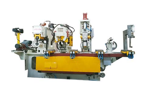
本设备由刨渣机、滚压机、端切机三部分组成,其中,刨渣机是车轮生产中的专用设备,用于除去轮辋焊接后产生的焊渣,从而得到平整的焊缝表面。焊缝滚压机用以压平并强化刨渣后的焊缝,经过滚压后焊缝和母材平齐。端切机用于切除焊缝两端头多余的焊接材料,冲切动作由油缸驱动
概述
Summary
本设备由刨渣机、滚压机、端切机三部分组成,其中,刨渣机是车轮生产中的专用设备,用于除去轮辋焊接后产生的焊渣,从而得到平整的焊缝表面。焊缝滚压机用以压平并强化刨渣后的焊缝,经过滚压后焊缝和母材平齐。端切机用于切除焊缝两端头多余的焊接材料,冲切动作由油缸驱动。
This machine is composed of trimmer, planisher and end cutting unit, which of trimmer is special equipment of steel wheel production for removing and trimming welding slag generated by wheel rim welding to obtain flat welding seam surface. Planisher machine is used to flatten and strengthen the welded seam after welding slag planishing and trimming. End cutting machine is used for cutting the both ends of redundant welding materials of welding seam, cutting action drives by oil cylinder.
规格参数
Specification
参数描述/Description Data
设备型号 model number BGQ-300-AH 额定输入电压 rated input voltage AC380V,3Phsae 额定输入频率 rated input frequency 50Hz 额定输入容量 rated input capacity 37KVA 工件厚度 Max. thickness of rim 5mm 工件宽度范围 width range of rim 220-320mm 工件直径范围 diameter range of rim φ280~φ450mm 刨渣夹紧力 maximum clamping force of trimmer 6Tons 刨渣力 maximum trimming force 6Tons 滚压夹紧力 maximum clamping force of planisher 6Tons 滚压滚压力 maximum rolling force of planisher 6Tons 端切剪切力 maximum cutting force of end-cutting 18Tons 端切剪切油缸直径 diameter of cutting oil cylinder of end-cutting 160mm 系统压力 system pressure 12Mpa
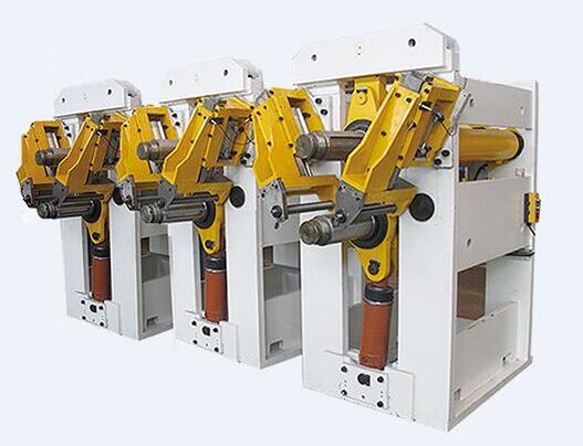
刨渣单元
Trimmer Unit
刨渣机是车轮生产中用于除去轮辋焊接后产生的焊渣,从而得到平整的焊缝表面。该机设计为自动操作,由主机、液压系统和电气系统等组成.其中液压系统和电气系统与滚压机、端切机共用。
Planning machine is special equipment of steel wheel production for removing and trimming welding slag generated by wheel rim welding so as to obtain flat welding seam surface. The machine is designed as automatically operation, it consists of host, hydraulic system and electric system, wherein hydraulic system and electric system are shared with rolling press machine and end cutting machine.
床身/Lathe Bed
主机架为C-型机构,液压驱动夹持器在焊缝两侧压紧。
Host frame is C-type mechanism. The hydraulic driven clamp holder clamps two sides of welding seam.
夹紧机构/Clamping Mechanism
工件由液压夹紧机构夹紧固定,该机构安装于导轨上方, 为阻止工件在刨渣时轴向松动、在夹紧钳口上装有止动块。
Work piece is clamped and fixed by hydraulic clamping mechanism, and the mechanism is installed on the upward side of guide rail. The stop block is installed on clamping jaw to avoid axial loosening of work piece during slag planning.
夹紧机构分上下两部,下部固定在机架床身,上部分为运动部分,由油缸驱动。
The clamping mechanism is divided into two parts, the lower part of which is fixed on the lathe bed of frame, the upper part is movable and driven by oil cylinder.
刨渣机构/ Trimming Mechanism
上下刨渣刀安装于钢制滑架上,此滑架由硬化处理的导轨支撑在夹持器中间来回运行,每个刀片的切割面根据材料厚度手动设定。
Upper and lower slag planning cutter is installed on steel sliding frame. The sliding frame makes to-and-fro movement in the middle of clamp holder by support of guide rail after hardening treatment, and cutting surface of each cutter is set manually according to material thickness.
刨渣刀具的切割面和夹持器采用一套机械机构相连,以保证其相对位置,这样无论何种厚度的材料,机器将不必每次设定,可自动适应切割不同厚度的材料。
Cutting surface and clamp holder of slag planning cutter are connected by one set of mechanic mechanism to ensure its relative position. Therefore, whatever any material thickness, the machine will not set each time, and can cut material with difference thickness automatically.
滑架上装有三组刀具,下夹持器为固定式,同时也作为下滑架导轨。上下刀具运动由液压缸驱动。
Three cutters are installed on sliding frame, and lower clamp holder uses fixed-type, and is also used as guide rail of lower sliding frame. Movement of upper and lower cutters is driven by hydraulic cylinder.
滚压单元
Planisher Unit
滚压焊缝机用以压平并强化刨渣后的焊缝,经过滚压后焊缝和母材平齐。滚压焊缝机的主要部件为:床身、可运动的C形框架、夹紧机构、滚轮及液压件。C形框架,装有液压驱动用以滚压固定于夹紧机构的制件的滚轮。
The planishing machine is use to flatten and strengthen the trimmed welding-seam, the planisher's main parts includes machine, movable C-type frame, clamping device, rollers and hydraulic parts. C-type frame equipped with hydraulic drive system for rolling roller that fixed on the clamping mechanism.
C形框架/ C-type Frame
C形框架固定于可沿导轨运动的支架上,油缸驱动,支架通过每边四个滚柱轴承滑动,C框架的主要功能是阻止滚压力的偏移及由此导致的滚压尺寸的偏移。
C-type frame fixed on the holder that can move along with the guide rail, it will be driven by oil cylinder. Holder can slide through roller bearing that set four (4) roller bearings each side. C-type frame's main function is to prevent rolling pressure skewing and the resulting rolling press size deviation.
端切单元
End Cutting Unit
床身/ Lathe Bed
C框架支持所有主要部件而且便于操作和调整。油缸固定在框架顶部用以驱动夹紧和冲切机构,可根据制件宽度调整的手轮调节机构装于框架尾部。
C-type frame supports all major components and it is convenient for operation and adjustment.
Oil cylinder fixed on the top of the C-type frame which is used to drive the clamping and cutting mechanism, and it can be adjusted according to the width of rim band, the hand wheel adjusting mechanism mounted on the tail of frame.
冲切机构/Cutting Mechanism
冲切机构通过切边模切除焊缝两端头。高压油缸(行程60mm)驱动上模,上下模间导柱一线性导套相连,上模固定于上模座,下模为下模座的一部分。前部刀具(上、下)固定于上下模座,后部刀具装于可动滑座上(可随制件宽度调节)。
Cutting mechanism cuts the both end of welding slag by cutting tool. The upper tool drives by high-pressure oil cylinder that stroke is 60 mm, upper tool (cutter) and lower tool (cutter) connects together by the linear guide pillar and guide sleeve. The front of the cutting tool (upper and lower) fixed on the upper and lower tool base, the back of the cutting tools installed on the movable slide base which can be adjusted according to workpiece width.
切边刀具由工具钢制作,每对刀具分别为凸、凹形状以逐步完成材料切边。上下刀具间隙应为料厚的8-10%,这样才能达到0.2mm的标准零件尺寸,间隙应该在刀具调节完毕后进行检查!
Cutting tools (cutter) made by tool steel, each pair cutter includes convex and concave shape tool, complete material cutting quickly. The clearance of upper and lower cutting tool should be 8-10% of the material thickness, for achieving the standard workpiece size at 0.2 mm.
NOTE: The clearance should be checked after cutting tool adjusting finished!
手轮调节机构/ Hand wheel Adjuster
手轮调节机构通过调节滑座位置以适应零件宽度的变化,包括气缸、尾座及其上的切边刀具,滑座可以通过框架后面的手轮而水平移动。
Hand wheel adjuster can adjust the sliding seat position to adapt the width change of work pieces, including air cylinder, the tailstock and cutting tools, sliding seat can move horizontally by the hand wheel at the back of frame.
冷却单元
Cooling Unit
气压驱动,杠杆结构。上下冷却铜板内通循环冷却水。
The cooling unit is driven by the air pressure and designed as lever structure. Inside upper and lower cooling cooper band has cooling water circulation.


 欢迎扫码咨询合作
 400-6586-222转8